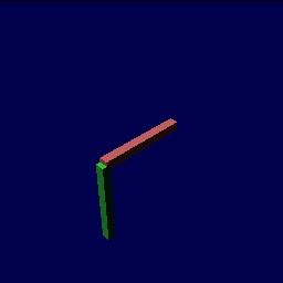
A rigid arm
A rigid arm
Block(1.0, 0.1, 0.1) : (color="red") {      // this block is long along X
  Translation(0.5,0,-0.5) {                 // blocks intersect at (0.5,0,0)
    Block(0.1, 0.1, 1.0) : (color="green"); // this block is long along Z
  }
}
Following the robotics standard, revolute joints rotate about the Z axis. For this reason, you must often rotate in and rotate out if you want to place a revolute joint in an existing design. Let's do this for the above arm, previously rigid.
Translation(-0.5,0,0),      // translate to endpoint of bar
 Rotation(1,0,0,-pi/2),     // rotate Z so it aligns with world Y
 RevoluteJoint,             // place a joint
 Rotation(1,0,0,pi/2),      // rotate back
 Translation(0.5,0,0) {     // translate back
  Block(1.0, 0.1, 0.1) : (color="red", mass=1) {
   Translation(0.5,0,0),    // do half our translation
    Rotation(1,0,0,-pi/2),  // rotate Z so it aligns with world Y
    RevoluteJoint,          // place a second joint
    Rotation(1,0,0,pi/2),   // rotate back
    Translation(0,0,-0.5) {  // translate to center of second block
     Block(0.1, 0.1, 1.0) : (color="green", mass=1);
    }
  }
}
To get the links to move, you must have an active gravity, and you must give the links non-zero masses.
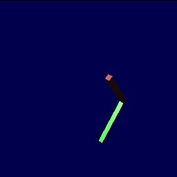
Double pendulum, 1 sec
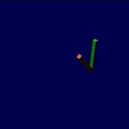
Double pendulum, 2 sec
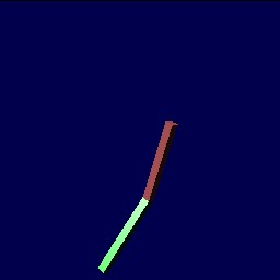
Double pendulum, 3 sec
The code for the second example looks a little hairy, but it can be cleaned up very easily if we rotate into the joints' coordinate frames, and never rotate out. I did the above to show that we can use the same blocks as in our previous example.