The CDL has a short list of various shapes one can use to input a robot's geometry. Let's first walk through each of the operations, with a description of their arguments. Then we'll discuss the parameters which are common to all of them.
Shapes
Let's start with the one shape we've already seen.
Block(x,y,z)
When given three arguments, a block of said dimensions will be oriented and centered at the current reference frame. Note that you must first translate if you wish the block to be positioned with a corner at (0,0,0) in the current reference frame.
If given a fourth argument, it is assumed to be a radius by which to extrude the block, smoothing the sharp edges. The difference can be seen in the following images.
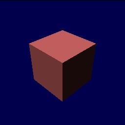
Block(1,1,1)
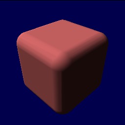
Block(1,1,1, 0.25)
Sphere(rad)
A sphere has only one required argument, its radius. The sphere is placed at the current reference frame.
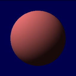
Sphere(1.0)
Cylinder(h,rad)
A cylinder needs two arguments, its height and its radius. The cylinder is centered at (0,0,0), and its height is along the z axis. An optional third argument can supply an additional extruding radius, similar to how the edges of a block can be smoothed.
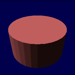
Cylinder(1.0,1.0)
Convex Hulls
Unlike the above operations, which are single function calls, a convex hull is different, since it can include any number of vertices. A convex hull is defined by two different operations, ConvexHull and Vertex(x,y,z). The former has an optional argument, the extruding radius for the whole hull, and the latter requires three arguments, a position. Vertex operations must be placed with the frame of reference of a ConvexHull. Not doing so is a syntax error.
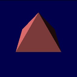
ConvexHull without extruding radius
ConvexHull {
  Vertex(1,0,0);
  Vertex(0,1,0);
  Vertex(-1,0,0);
  Vertex(0,-1,0);
  Vertex(0,0,1);
}
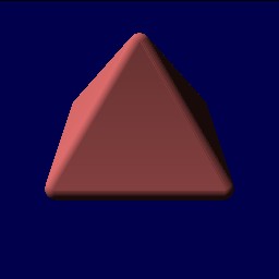
ConvexHull with extruding radius
ConvexHull(0.25) {
  Vertex(1,0,0);
  Vertex(0,1,0);
  Vertex(-1,0,0);
  Vertex(0,-1,0);
  Vertex(0,0,1);
}
Common Parameters
Now that we are working with shapes, we have a few additional parameters we can pass to the operations.
- name="name" : the name of the object. This is stored internally in the simulator, so you can later retrieve the object by name, or reference it from other points in a CDL file.
- color="colorname" : as of this writing, limited to green, yellow, red, blue and black. Near future plans call for adding the ability to specify any color, as well as to specify surface textures.
- mass=m : gives the associated object a mass of m. When working with blocks, spheres, and cylinders, the mass is distributed according to the shape of the object. When working with convex hulls, the mass is a point mass centered at (0,0,0) in the current reference frame. Take this in mind when designing your convex hulls! (i.e. don't make them too big, and don't offset them too much from (0,0,0)).
- surface="surfacename" : this will tell the simulator which surface type to use for the object. Surface types are defined using the DefineSurface operation, described later. No other parameters are needed here at the object.
SimLib Reference Documentation