Section 2.2 Creating Regions
This section takes a hands-on approach to walk you through the basics of creating regions in the GUI.
Starting the GUI
Start the GUI by running main.py. See Chapter 1 Installation for instructions.
Creating a New GSSP Program
Click File -> New.
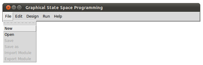
You should see the New Program dialogue.
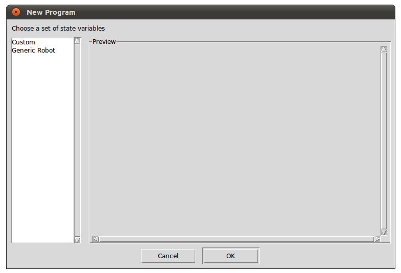
The New Program dialogue allows you to choose a set of state-variables to work with. In Section 2.7 Customizing State-variable Sets, we will look at how to create your own state-variable set. For now, click on Generic Robot. You should see the following:
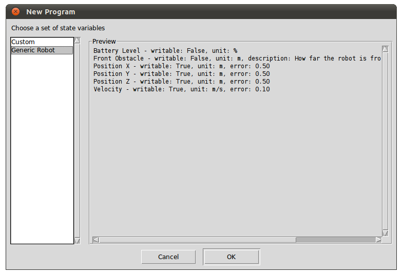
Click OK.
You have just created a new GSSP program.
Creating One-dimensional Regions
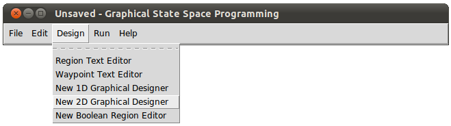
Click Design -> New 1D Graphical Designer.
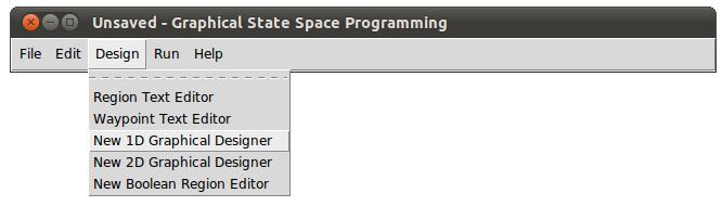
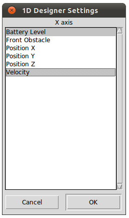
You should see the 1D Designer Settings dialogue.
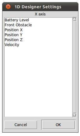
Designer Settings dialogues allow you to specify which state-variable(s) you want to work with. For the purpose of this tutorial, click Battery Level to select it.
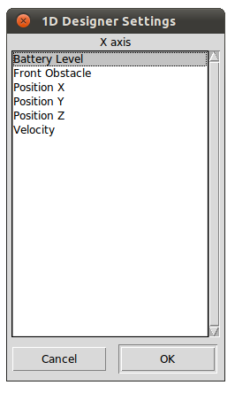
Click OK.
You should see the following 1D Designer.
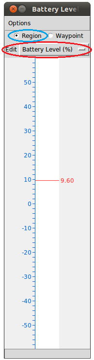
Notice that there is a white area in the middle and a vertical axis to its left. The white area will be referred to as the drawing area. To pan, drag any number along the axis vertically with the left mouse button. To zoom, drag with the right mouse button vertically on the drawing area. The Edit Pull Down Menu, circled in red in the figure above, displays the state-variable this designer works with.
To create a region, first make sure that the Region Radio Button is selected. The Region Radio Button is shown in the blue circle in the figure above. The Region Radio Button is selected by default and indicates that you are working with regions. You can create a region by dragging with the left mouse button vertically on the drawing area. Try creating a region from approximately 10 to 30. You should end up with something that resembles the following figure. The color of your region is randomly generated so it could differ from the figure. If you make a mistake, press control-z to undo. To redo, press control-r.
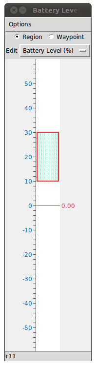
You have just created a one-dimensional region. It is one-dimensional because it represents a constraint on one state-variable, namely Battery Level.
Create another region from 40 to 50. You should end up with something like the following.
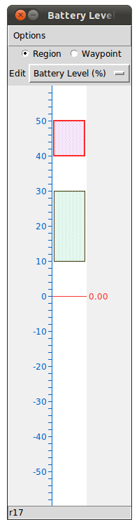
Notice that one of the regions is outlined in red, and the other is outlined in black. The region outlined in red is the selected region. Only one region can be selected at a time. To select a region, make sure the Region Radio Button is selected, then left click the region you wish to select. Try selecting the other region.
Creating Two-dimensional Regions
Click Design -> New 2D Graphical Designer.
You should see the 2D Designer Settings dialogue.
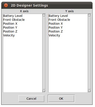
Choose Position X for the X axis, and Position Y for the Y axis, as shown in the following figure.
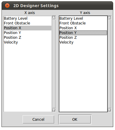
Click OK.
You should see the following 2D Graphical Designer. Note that the X axis is the horizontal axis, and the Y axis is the vertical axis.
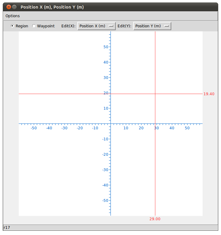
Like the 1D Graphical Designer, there is a white drawing area. You can pan by dragging any number along either axes in any direction with the left mouse button. You can zoom by dragging the right mouse button vertically on the drawing pad, just like the 1D Designer. There are two Edit Pull Down Menus - Edit(X) and Edit(Y) - displaying the state-variable on each of the two axes.
To create a region, first make sure that the Region Radio Button is selected, then drag the left mouse button diagonally on the drawing pad. Try to create a region where Position X is between 10 and 20, and Position Y is between 20 and 40. You should end up something like the following.
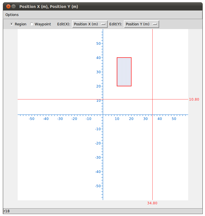
You have just created a two-dimensional region. It is two-dimensional because it represents constraints on two state-variable, namely Position X and Position Y.
Notice that when the newly created region is selected, the two regions we created earlier are no longer selected.
Creating Multi-dimensional Regions
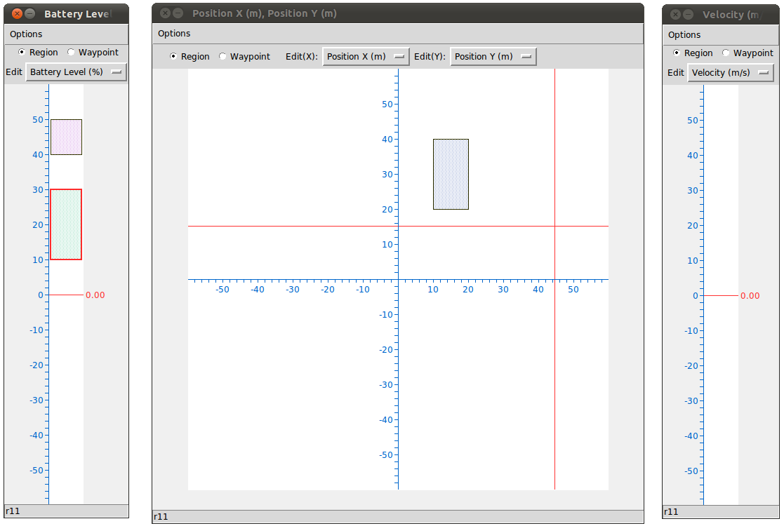
Open another 1D Graphical Designer, and choose Velocity for the 1D Designer Settings dialogue. You should now have three graphical designers open: Two 1D designers, and one 2D designer, as shown in the following figure.
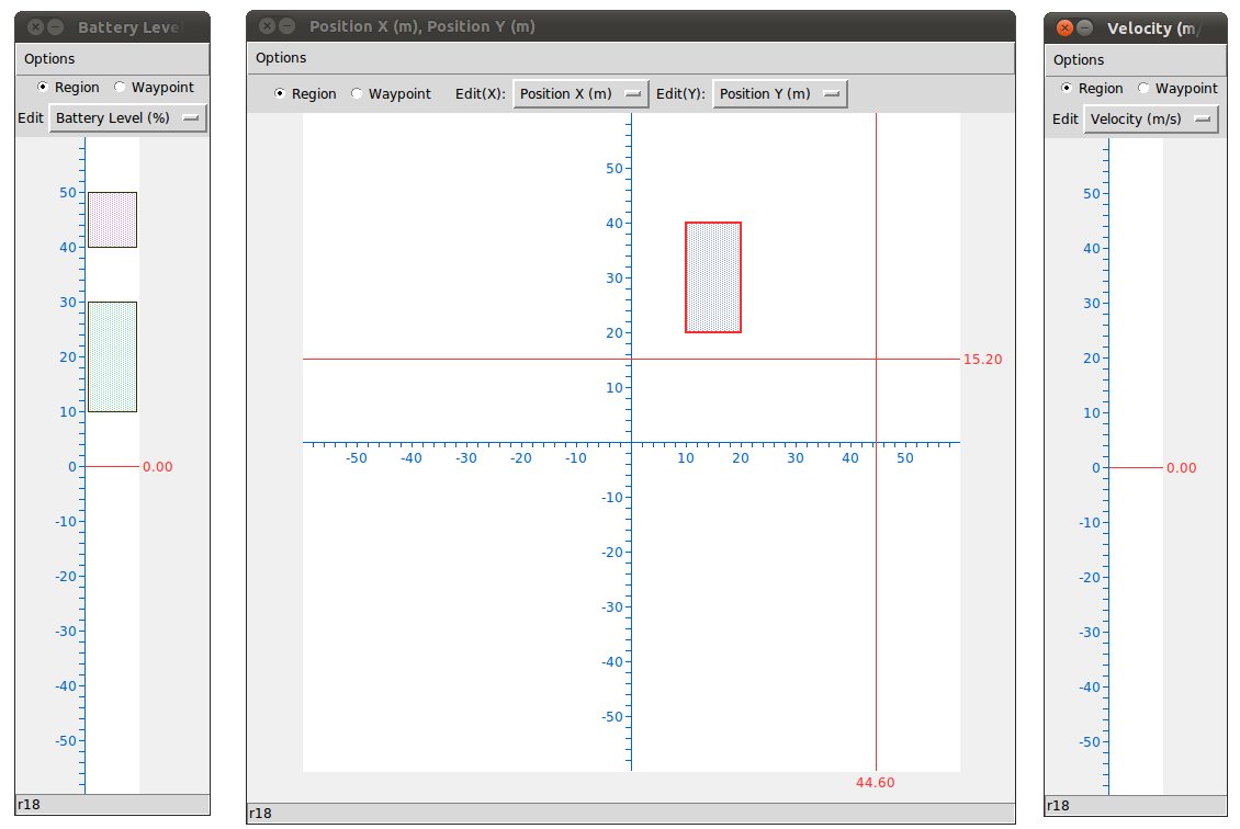
Make sure that the Region Radio Button is selected for all three graphical designers.
Select one of the region we created earlier in the 1D designer for Battery Level. It should be outlined in red as shown in the figure below.
Then, while holding down control, create a new region in the 2D designer for Position X and Position Y. You should end up with something like the following figure.
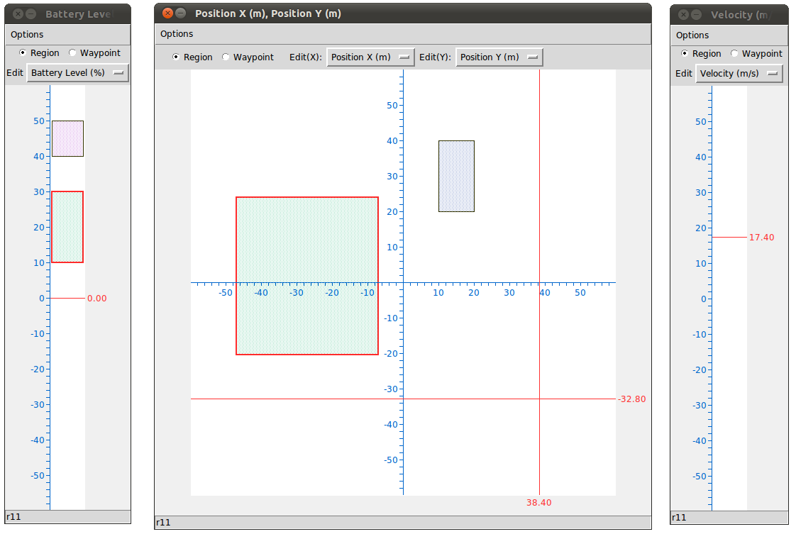
Notice that both of the designers now have a rectangle outlined in red. As aforementioned, only one region can be selected, implying that the two rectangles represent the same region.
You have just created a three dimensional region. Let's add one more dimsion to the region.
While the region is selected, hold down control, and create a region in the designer for Velocity. You should end up with something like the following figure.
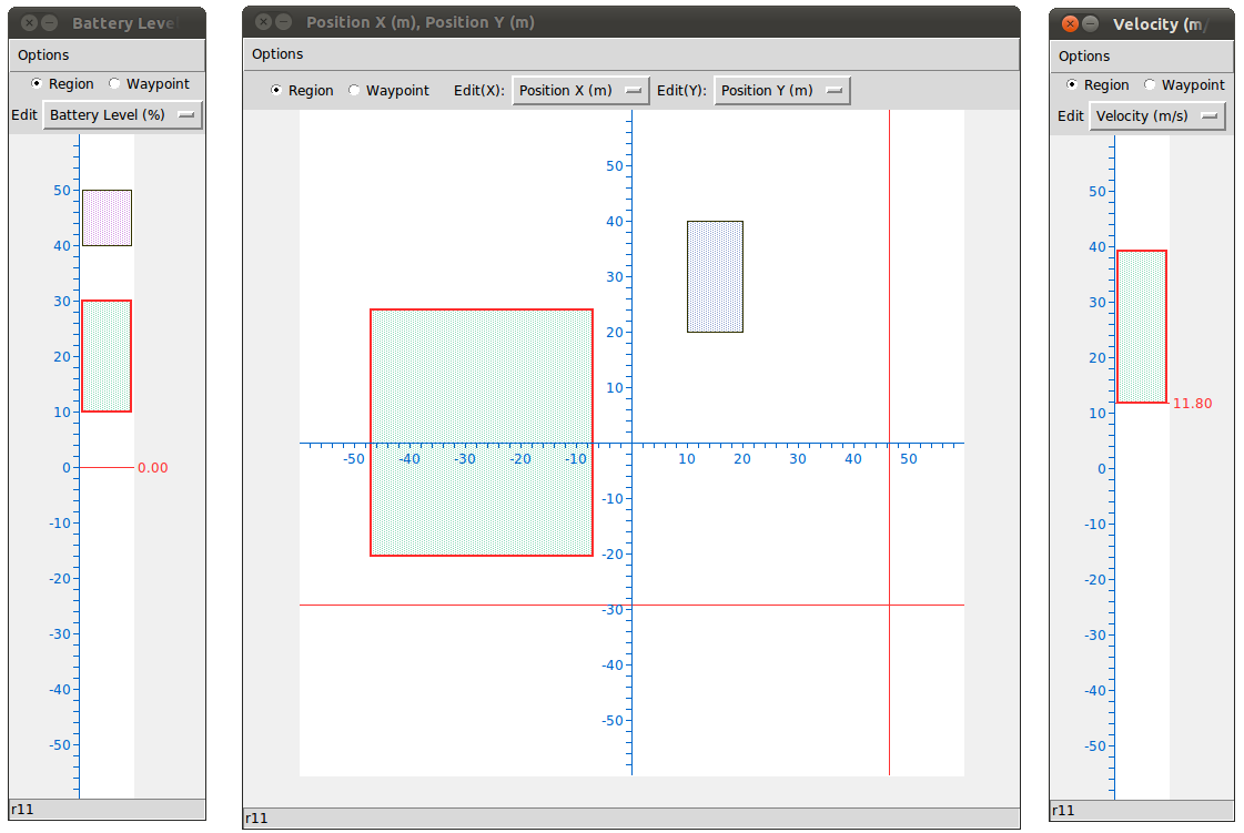
You now have a four-dimensional region. You can use any combination of an arbitrary number of 1D and 2D designers to create regions of any dimension.
Deleting Dimensions from Regions
Suppose we want to remove the Velocity dimension from our four-dimensional region. To do this, middle click the region inside the 1D designer for Velocity. You should end up with something like the following figure.
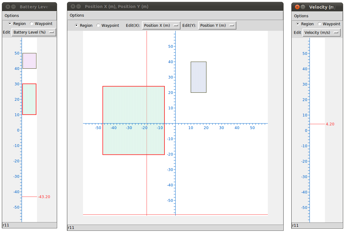
The four-dimensional region has become a three-dimensional region, with constraints on Position X, Position Y, and Battery Level. If you middle click this region in the 2D designer for Position X and Position Y, then constraints for both Position X and Position Y will be removed, and you will be left with a one-dimensional region with a single constraint on Battery Level.
If you delete all the dimensions from a region, the region will no longer be visible in the graphical designers. However, the region still exists, and is a zero-dimsional region. We will talk more about zero-dimensional regions later on.
One-sided Inequality
All the regions that we have created thus far implement two-sided inequalities. Consider the first region we created, where Battery Level ranges from 10 to 30. This could be seen as the following two-sided inequality.
10 ≤ Battery Level ≤ 30
Sometimes, we need one-sided inequalities. For example, to capture the situation where Velocity is too high, we might want something like the following one-sided inequality.
50 ≤ Velocity ≤ positive infinity
Let us implement some one-sided inequalities using the graphical designers.
Create a region ranging from 30 to 40 in the 1D designer for Velocity. Then, while the region is selected, press the upward arrow button on the keyboard. You should end up with something like the following figure.
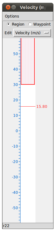
As you can see, the region no longer has an upper bound. This region represents a one-sided constraint that can be seen as:
30 ≤ Velocity ≤ positive infinity
Pressing the downward arrow button would have created a region with no lower bound, representing the following constraint:
negative infinity ≤ Velocity ≤ 40
If you press the upward arrow, followed by the downard arrow (or the the other way around), the region will disappear from the designer. This is because doing so, you will have created the following constraint on Velocity:
negative infinity ≤ Velocity ≤ positive infinity
However, such a constraint is no constraint at all, since Velocity is always between negative infinity and positive infinity. Thus, the constraint for Velocity will be removed, and you will end up with a zero-dimensional region.
Now, create a region in the 2D designer for Position X and Position Y. Then, while the region is selected, press the left arrow button. You will see that the lower bound for Position X is gone. Pressing the right arrow button will remove the upper bound for Position X. The upward and downard arrow buttons will remove the upper and lower bound for Position Y. If you press all four arrow buttons in sequence, the region will disappear for reasons similar to the one-dimensional case.
Working with Multiple State-variables per Axis
It is possible to work with multiple state-variables on each axis. Click Design -> New 1D Graphical Designer. On the Designer Settings dialogue, click Battery Level and Velocity. You should end up with something like the following figure.
Click OK.
This designer should show all the regions for both Battery Level and Velocity. The Edit Pull Down Menu allows you to choose which of the two state-variables you wish to edit. For example, if you choose Velocity, and then create a region in the designer, then the region will be for Velocity.
You can also choose to work with multiple state-variables on each of the axes of a 2D Graphical Designer. The 2D designer will then pair up each state-variable on the X axis with each state-variable on the Y axis and visualize all the regions that have constraints on each pair of state-variables. This is not usually a helpful visualization, and should be avoided in most cases.
Region Text Editor
The Region Text Editor should have been opened when you started the GUI. If you've closed it, you can open it again by clicking Design -> Region Text Editor. You should see the following window.
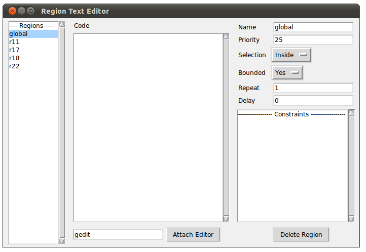
Region List Box
To the left is the Regions List Box that lists all the regions that exist in your GSSP program. Recall that zero-dimensional regions are not shown in the graphical designers. Zero-dimensional regions are shown here. You will see a region here called global. This region is a zero-dimensional region and is automatically created when you create a new GSSP program. Since it is zero-dimensional, it will be satisfied immediately when the robot begins operating, and its attached code will be executed. Thus, you can attach initialization operations to the global region.
Try selecting a region in any graphical designer. You will see that the selected region is automatically selected in the Region List Box. Now try clicking on a region in the Region List Box. You will see that the region automatically gets selected in the graphical editors as well.
Name Text Field
You can rename any region using the Region Text Editor. First, select a region, either by clicking on it in a graphical designer, or by clicking it in the Region List Box. Then, enter a name in the Name Text Field at the top right corner. Notice that the change gets reflected in the Region List Box.
Constraints List Box
At the lower right is the Constraints List Box that shows all the constraints of this region. You can click on any constraint and edit it. The changes will be reflected in the graphical designers. Note that you can enter inf to denote infinity.
Delete Region Button
At the bottom right corner is the Delete Region Button. Clicking this button will completely delete the selected region.
Code Text Area
In the center of the Region Text Editor is the Code Text Area that you can use to attach code to regions. While a region is selected, write code in the text area to attach code to the region. The Python programming language is used to write code in GSSP. You can write any valid python code and import any python library. We will talk more about this in the next section. Section 2.8 Writing Code in GSSP will describe built-in functions and variables that you can use when writing code in GSSP.
Attaching External Editor
The text area for writing code is very primitive so you are encouraged to use your own editor when writing code in GSSP. To do so, select a region for which you want to attach code. Then, enter the command that starts your preferred text editor in the text field below the text area, then click Attach Editor. You will see the code that you've already written appear in your preferred text editor. When you are done, save your edits in your preferred text editor, and then click Release Editor in the GUI. You will see your edits transferred back to the GUI. Please note that in order to use this feature, you must be able to run
editor my_file
at the command line, where editor is your preferred editor, and my_file is some arbitrary file. For those who use Eclipse, you will not be able to use Eclipse here because you cannot run a command like "eclipse my_file" and have Eclipse open my_file.
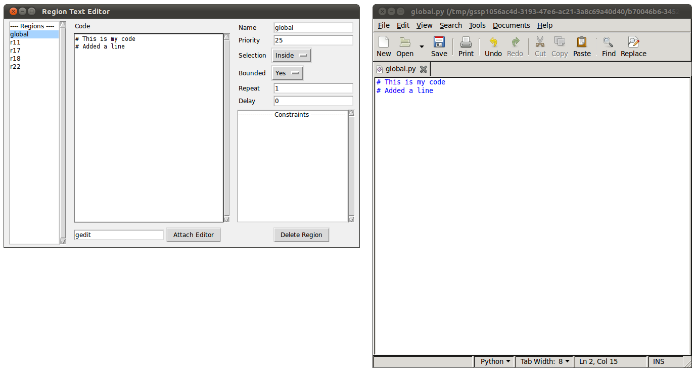
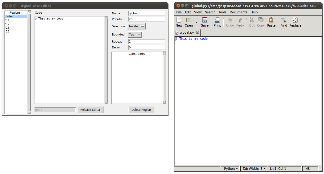
The figure below shows an example in Ubuntu. gedit is entered as my preferred editor.
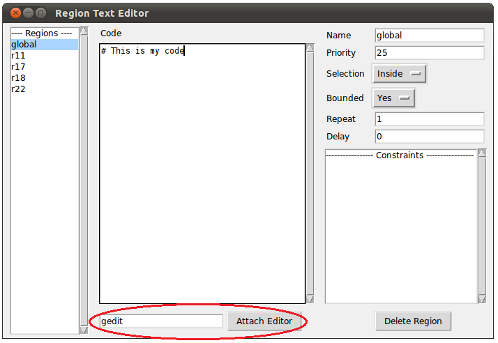
When you click on Attach Editor, gedit will open, showing what you had in the Code Text Area, as shown in the following figure.
In the following figure, the code has been edited and saved in gedit.
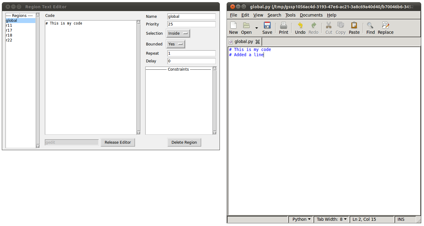
Now, if we click save in gedit, and then click Release Editor in the GUI, the updated code shows up in the GUI, as shown below.